Back in 2011 Adaptronic started designing their next generation ECU. The main objective was to work towards their mission which is to give people control. In doing this, Adaptronic came up with a system which would give people greater flexibility and at the same time, overcome the limitations of their older product line, the Select ECUs.

The original goals for the new model were:
-
Modular system, so that people can buy hardware upgrades later as their needs develop (eg additional inputs, outputs, or specific functions that we won’t force everyone to buy, eg drive by wire or built-in lambda)
- Offer a IP67 waterproof option using Superseal connectors
- Retain the design flexibility to build plug-in ECUs easily
-
Complete new units from the ground up, including new software( Eugene)

And in addition, several “processing” ideals:
-
"Wifi" Wireless communication
- Faster USB communication, requiring no drivers
- 4x serial in ports
- Up to 2x CAN port
- 32MB of on-board logging to flash
-
Exception logging, so being able to detect faults and log a bunch of things that happen around the same time to help with ECU setup and tech support( separate from main integrated logging)
-
Bigger maps( 32 x 32), more of them, and more dedicated maps.
-
Built in Oscilloscope; to aid in external hardware & wiring faults etc
- User definable gauge displays & maps with warning presets
- Up to 24 ignition & 24 injection drivers
- Up to 86 total outputs
- 4 VVTI channels
- 4 Electronic throttle body channels
- Built in Engine Simulator
- Advanced trigger fault detection with variable filtering etc
-
Arbitrary Logic Function( easier version of the advanced mode in the current E1280s- the ability to implement any software logic you want- in development).
- Retain the ability to power the ECU over USB to do loading of maps, firmware etc without having to provide it with 12V power
- Retain the headphone port as on current Adaptronic models

And on the engine interface side of things:
- More inputs standard; consistent with our value of “encouraging the right way”, we should have fuel pressure, exhaust back pressure etc as standard inputs
-
2nd built in 4 bar map sensor for dedicated EMAP( exhaust manifold back pressure)
- More outputs standard; again we should be encouraging people to run 6+ cylinder engines fully sequentially with direct fire
- Increased processor speeds
- Greater built in protection against end user voltage spikes, wiring faults, EMI, etc
- PNP models will have in house tested lag settings for Modular injector drivers
- 3 axis accelerometer (G sensor) and rate gyro

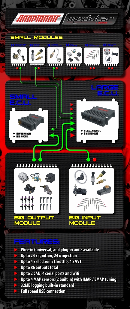
So with this in mind, we present the new Modular ECUs; M2000 & M6000
M2000– space for 1 large module (8 injector, 8 ignition, 4 aux) + 1 small module (for user expansion)
M6000 – space for 3 large module (8 injector, 8 ignition, 4 aux, plus 2 x user expansion) + 4 small modules (for user expansion)
All of the ECUs have:
- 1 Control module
- 16 analogue inputs, including a knock input
- 2 x built-in 4-bar MAP sensors( 1 for intake pressure & 1 for exhaust pressure )
- ECCS / fuel pump and tacho outputs, but no other outputs
- 3 axis accelerometer (G sensor) and rate gyro
- Space for 1 or more large modules, of which one will be an output module:
- 8 peak and hold, switching mode injector outputs (unused injector outputs can be PWM low side drive outputs)
- 8 current limited ignition outputs (unused ignition outputs can be PWM low side drive outputs)
- 4 current limited push-pull outputs (can be PWM)
- ANALOG: EGT and 0-5V inputs (number of each not finalized yet - in development)
- Space for 1 or more small modules, which can be
- Additional 6 push-pull PWM outputs
- Single channel Drive by wire controller ( in development)
- Lambda controller ( in development)
- Additional real-time inputs (for additional VVT channels, multiple vehicle speed inputs, flex fuel etc)
- SMALLRT: 2 x additional cam sensor inputs, 1 x dedicated flex input, 3 x additional wheel speed inputs ( in development)
- PNP( plug and play models) – all contain one large module, others as required depending on the application, and additional spaces for modules depending on the number of spare pins on the factory connector

Features / Specifications
Control board (1 per ECU)
| Variable |
Number |
Details |
| Analogue 0-5V inputs |
11 |
Each is 0 – 5.5V, 55k input impedance
- 2 x TPS / pedal position
- 6 x pressure – Oil, Fuel, Internal intake MAP, internal exhaust MAP, external intake MAP, external exhaust MAP
- 3 x spare for servo feedback / external inputs
|
| Analogue oxygen sensor inputs |
2 |
Each can be either:
- 0 – 5.5V, 55k input impedance
- 0- 3.3V, 1M input impedance
|
| Temperature inputs |
4 |
Each is 0 – 5.5V, 55k input impedance to ground
Each can be:
- Non-biased, eg in piggyback mode. Calibration is in mV
- Biased, calibration is in Ohms. 3 internal pull-ups, 1k5, 2k2, 4k7, automatically selected by the ECU
Manifold air temperature, coolant temperature, oil temperature, fuel temperature
|
| Crank trigger inputs |
3 |
- Selectable 2k2 pullup (on in digital mode, off in reluctor mode)
- Variable voltage trigger threshold from 0 to 65V – either arm input for reluctor or threshold for digital input
- AC coupled zero crossing trigger in reluctor mode
- Variable filtering 1 to 192 µs
- See built-in scope section
|
| Vehicle speed input |
1 |
- Selectable 2k2 pullup
- Variable voltage trigger threshold from 0 to 65V
- Variable filtering 1 to 192 µs
- See built-in scope section
|
| Sensor power and ground |
|
- 5V regulated output for sensors, max 100 mA, current limited (voltage is monitored by ECU)
- Sensor ground connected to ground inside ECU under firmware control to detect external ground loops in the wiring (voltage is monitored by ECU)
|
| Knock inputs |
1 |
- 50 k input impedance
- Sampled at 80 kHz (12-bit resolution, 3.3V peak to peak max voltage),
- Variable second order highpass and lowpass filters
- Selectable start and end of sampling windows (in crank angle)
|
| Wired Outputs |
2 |
- Dedicated outputs for tacho and EFI relay
- Tacho output has inductor to generate back-EMF spike for impulse tachometers.
- EFI relay output can be configured as fuel pump or EFI relay. Switches to ground, current limited to 600 mA
|
| Headphone output |
1 |
Mono output, can be selected as direct knock input or filtered knock input |
| Power sources |
3 |
ECU can be powered by 12V EFI input, ignition switch, or USB (USB for settings / firmware upgrades / log retrieval only; 12V must be applied to read inputs) |
| CAN channels |
2 |
- Up to 1 Mbps
- Internal 120 Ohm terminating resistor can be turned on and off with ECU setting on each channel
|
| USB connection |
1 |
- Standard USB mini AB connector.
- 12 Mbps max speed
- USB appears as mass storage device (USB stick); no drivers are necessary
- Software installer included on mass storage device
|
| Serial connections |
4 |
- All 4 use 4-pin Molex connectors
- 2 x serial in (ground, transmit, receive)
- 1 x serial out (ground, transmit, receive)
- 1 x controller out (ground, transmit, receive and 12V switched, current limited power) – eg for dash, hand controller
|
| Wireless connection |
1 |
- Access point
- 230kbps max speed
- Settings and live data only (no log retrieval due to speed)
|
| Inbuilt sensors |
|
- Microphone
- 3 axis accelerometer
- 3 axis rate gyro
|
| Inbuilt logging |
32 MB |
- Max 30 hrs @ 10 Hz, 13 channels
- Min 20 mins @ 100 Hz, 125 channels
|
| Exception (fault) detection |
16 MB |
Separate logging memory for storing logs during “exceptions” (sensor / trigger faults etc) |
| Built-in scope |
4 channels |
- Max sample rate 200 kHz (5µs sample period)
- 1000 samples per screen (min 5ms across the screen)
- Analogue trigger inputs sampled at 40 kHz
Channels include
- Analogue CAS inputs
- Peak detected CAS voltages
- CAS threshold voltages
- Filtered CAS inputs
- Analogue external inputs
- Raw and filtered knock waveforms
- Current engine angle
- Calibrated input values
- Intermediate calculation values
- Output calculated values
|
| Main loop execution speed |
|
Variable depending on tuning mode and corrections enabled, 400 Hz nominal |
Output Module (1 or more per ECU, max 3)
| Number of injector outputs |
8 |
- Switching topology for low heating
- Peak and hold current waveforms
- Programmable peak and hold current
- Max current per channel 4A continuous
- Nominal current per channel 1A (can be controlled in software)
- Unused injector outputs can be configured as auxiliary outputs, PWM capable, but only switching to ground
- Output voltage and current monitored
|
| Number of ignition outputs |
8 |
- Appears as a 470 Ohm to supply when high, short to ground when low
- Current limited output
- Unused injector outputs can be configured as auxiliary outputs, PWM capable, but only switching to ground, and only low current
- Voltage and current monitored
|
| Number of aux outputs |
4 |
- Push-pull outputs (can drive high or low)
- High side current limited to 1.2A
- Low side current up to 4A continuous
- Can be PWM but not engine synchronous
- Voltage and current monitored
|
Mini Output Module (1 or more per ECU, max 3)
| Number of aux outputs |
6 |
- Push-pull outputs (can drive high or low)
- High side current limited to 1.2A
- Low side current up to 4A continuous
- Can be PWM but not engine synchronous
- Voltage and current monitored
|